
|
 |
||||
I was able to dedicate all of today on the project - something that has not occurred in some time. I really got a lot completed. First off, I started working inside installing the Airflow Performance pump and filter along with all of the check valves and pressure regulators. It's a pretty complex setup. 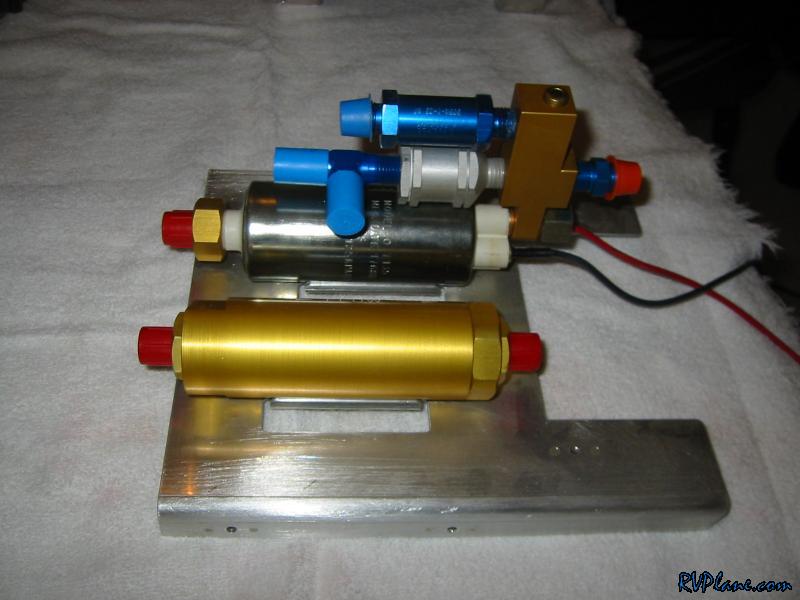 The first thing I notices was the fuel filter didn't sit nicely on the bracket as the fuel pump does. Now there are some rubber strips that protect the filter and pump from the metal, but still, I thought it was a little sloppy. 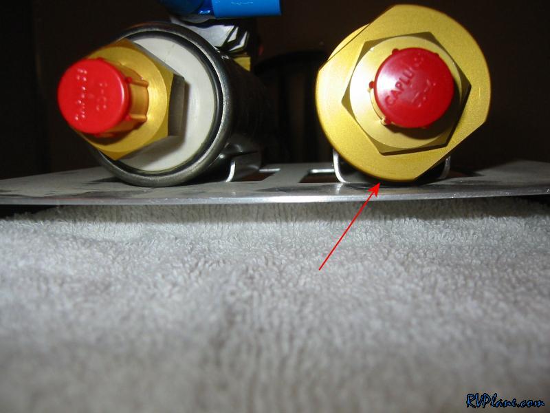 After some fun with bending 063, the filter looked much better. 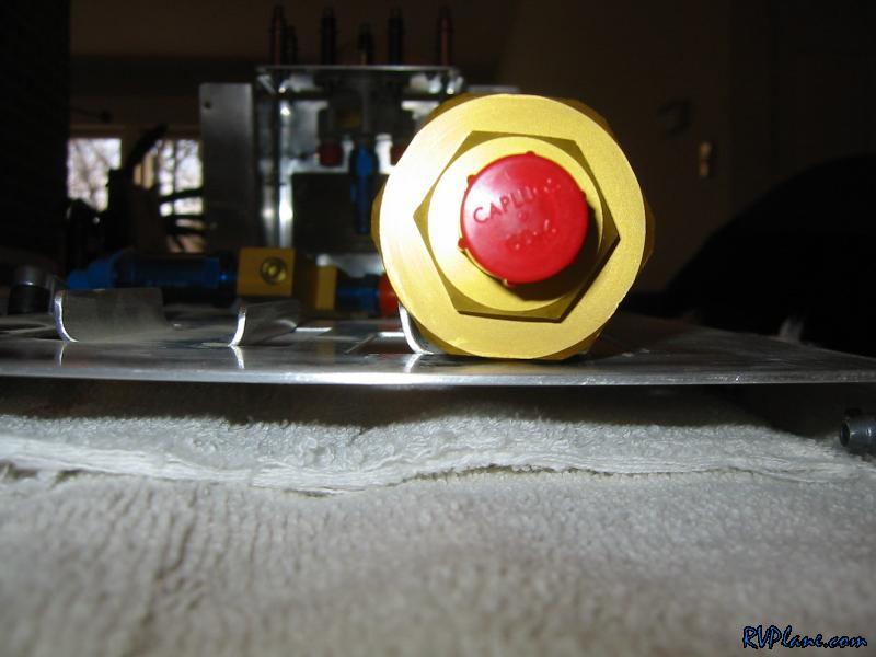 Next was installing the regulator, checkvalve and other fittings onto the manifold. I used fuel lube on all of the connections. 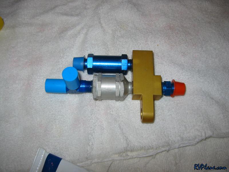 Next I attached the manifold to the fuel pump. 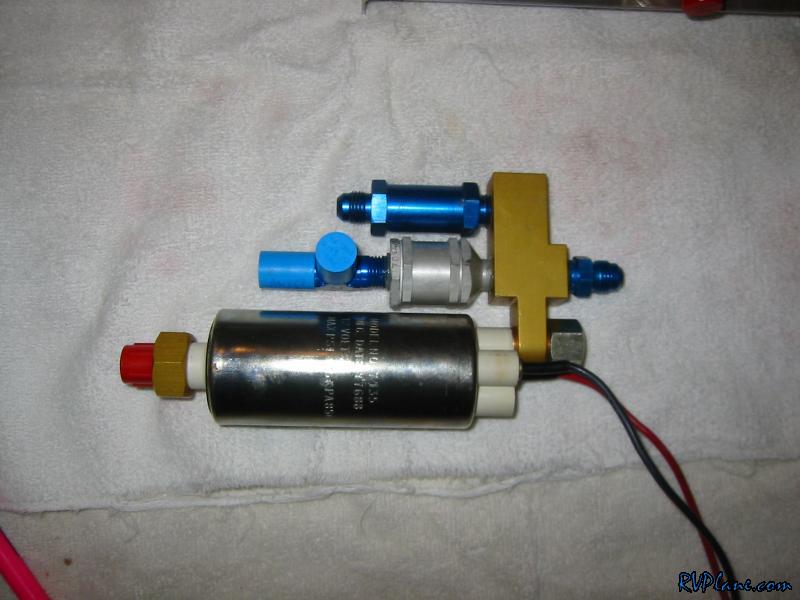 Now onto fun with tubing. This is the fuel input to the pump. This tube was a real bear to make. I bought all of this stuff piecemeal, so the tube wasn't premade for me. From what I understand, the tube is made for you by Airflow Performance if you buy the kit from Van's. 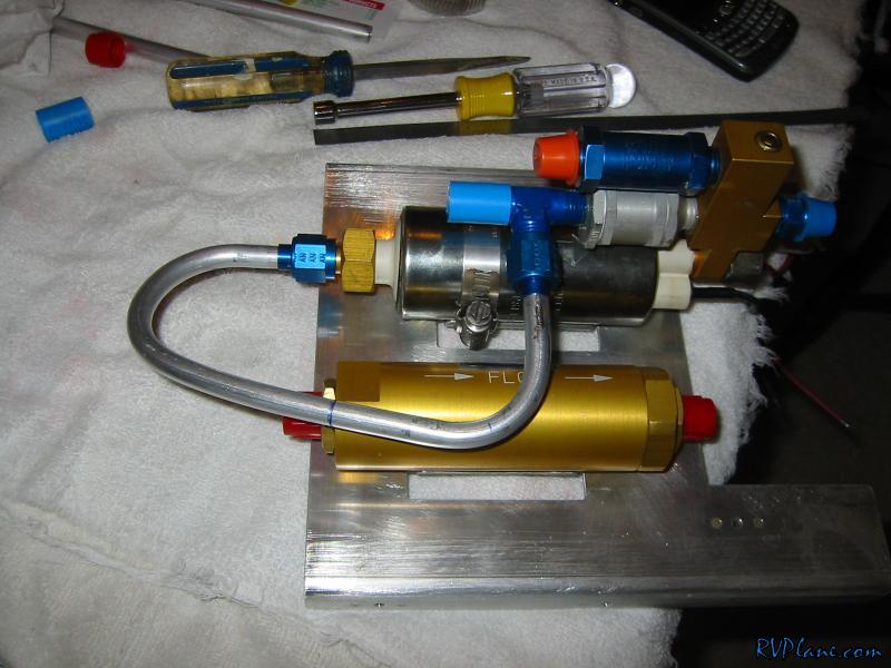 Here is another view. The tube went way to the left side of the bracket. 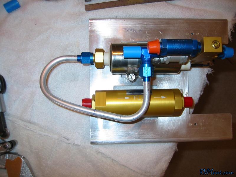 Next was the tube from the filter outlet to the inlet of the pump. When the pump is off, the checkvalve is used to bypass it and go right through the manifold. 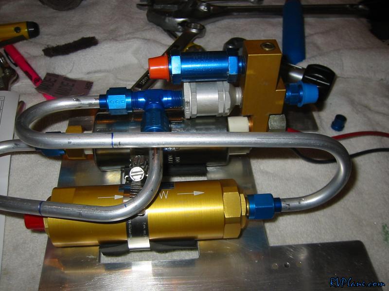 Next I got the cover for the AFP pump and put it on to see how to route the lines to the fuel selector valve. 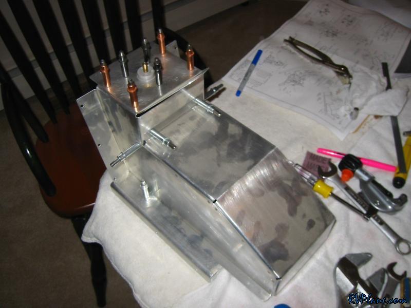 Since I am using the Andair fuel selector valve, my setup is a little different than the Van's stock valve setup. 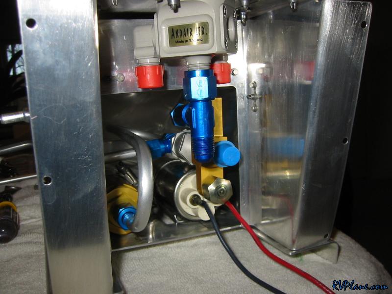 Here is the tube from the pressure relief valve to the T fitting on the bottom of the fuel selector valve. This tube is to allow any additional fuel (beyond the 25 or so PSI the relief valve is rated for) to be returned back to the upstream source of fuel. Basically, if the fuel pump generates too much pressure, it gets fed back to the supply tank. 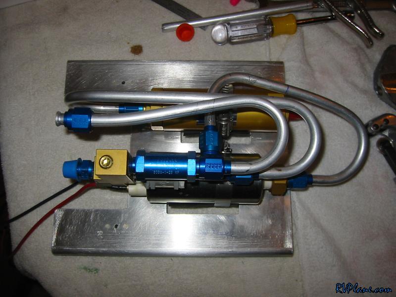 Here is it connected to the T fitting. 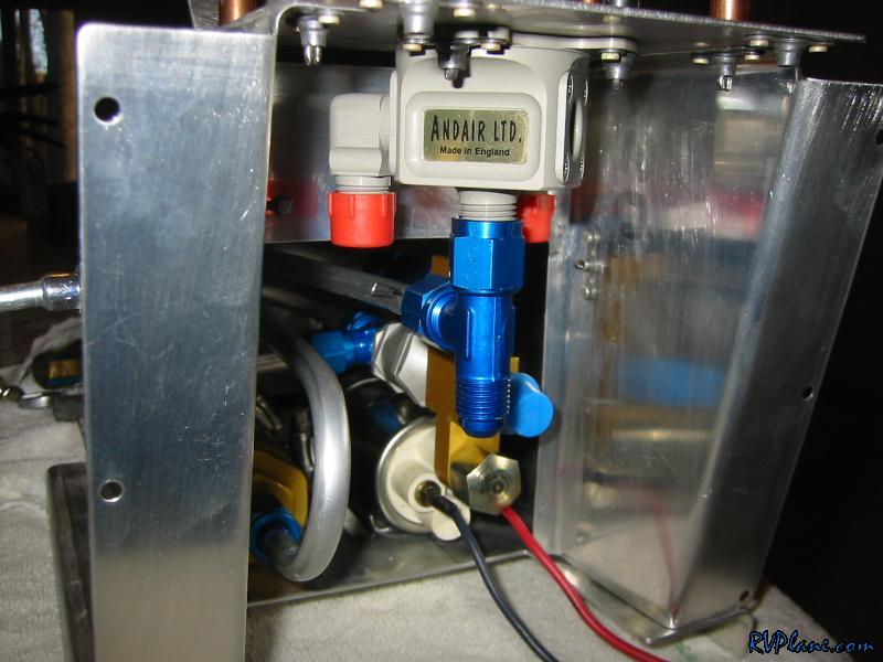 Another shot. 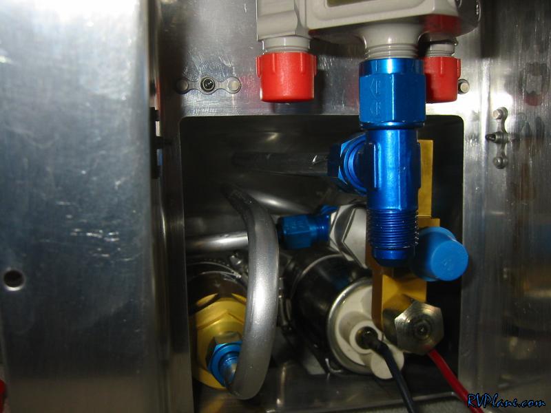 With that set, I could remove the T from the fuel selector valve and keep it in position for the next run. 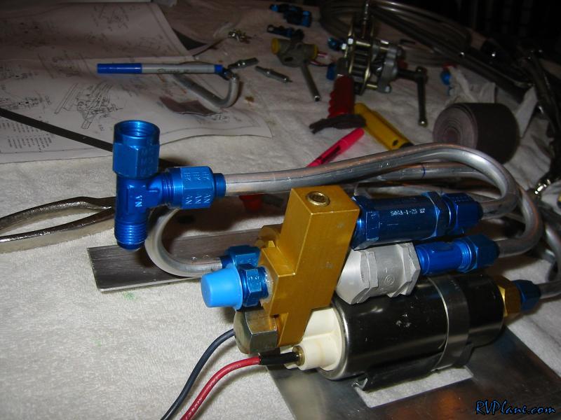 And here is the feed to the input to the filter. 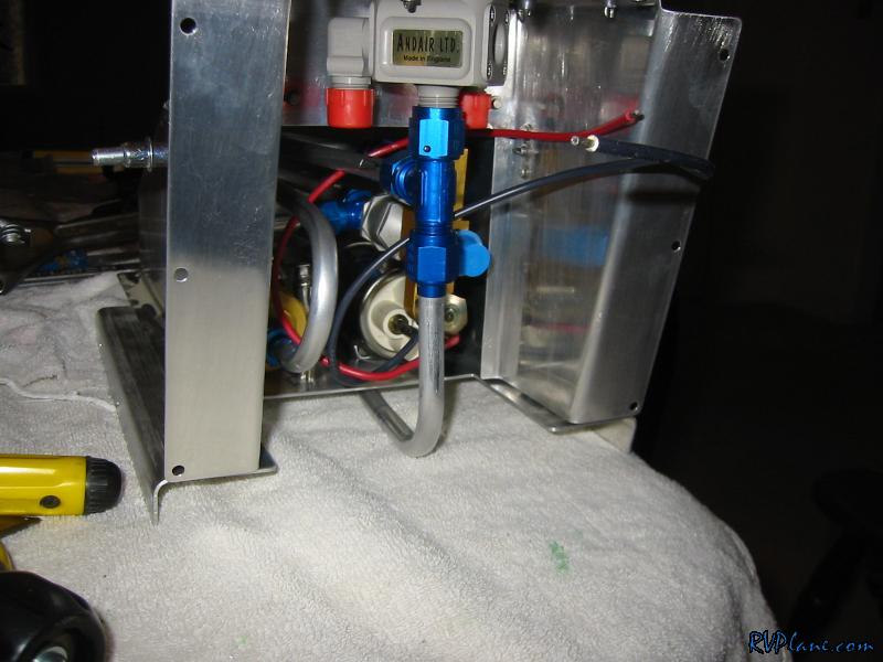 Another shot. 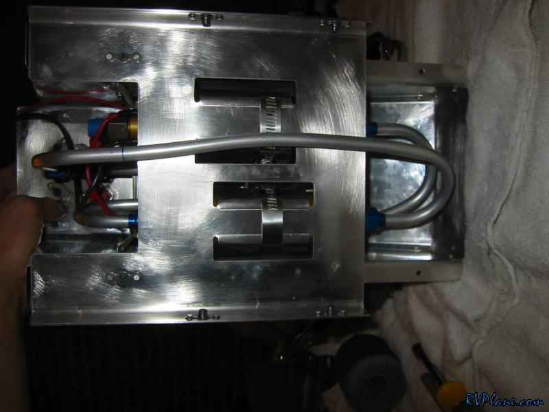 And here is the complete system. 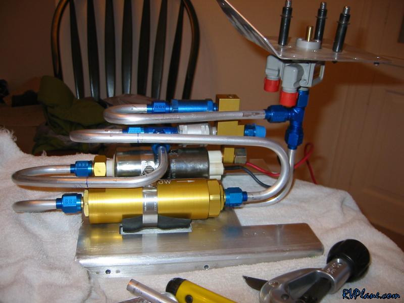 While I was warmed up making tubing, I decided to brave the cold garage and bend the tubes from the tanks to the fuel selector valve. You can see I used unions to simplify my life. 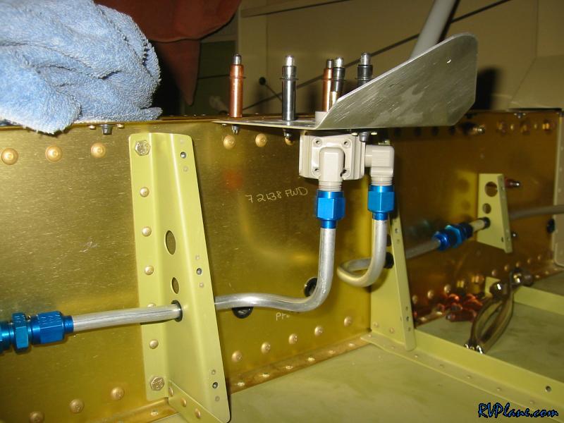 Here is another shot. I highly recommend using the unions. They make your life so easy. And if you ever have to redo one of the runs, it would be a snap to do. 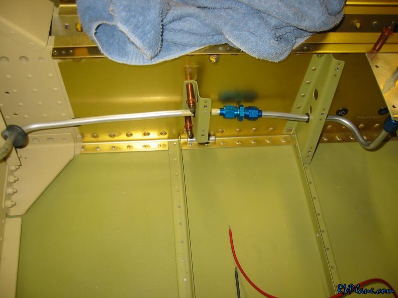 Ugh, I knew my luck was too good today. There was interference between the right tank feed and the outlet fitting from the manifold. I din't know why I didnt take a pic, but I put a 90 degree fitting here, pointed downward, and that fixed the issue. There is a pic down the page a little. 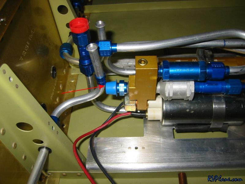 Next I cut a notch in the front of the bracket that holds the fuel pump and filter. I wonder what this is for?? 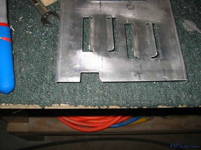 I decided to put my fuel flow transducer here. Some people put it in the firewall, some people put it here. I liked it here a lot better. Supposedly it will be a little less accurate here as opposed to in the firewall, but I was really concerned about it heating up and causing vapor lock. Hmmmmm........a very little inaccuracy or vapor lock? Easy choice. 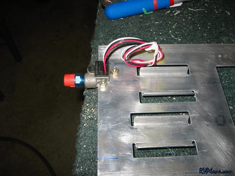 Here is a shot from the bottom. These AN3 bolts are jump temporary to hold things together. 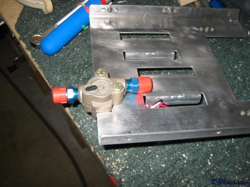 The hole in the fuel flow transducer is 1/4", but I didn't want to use 1/4" bolts. So I used some 1/4" aluminum tubing and made a quick bushing. 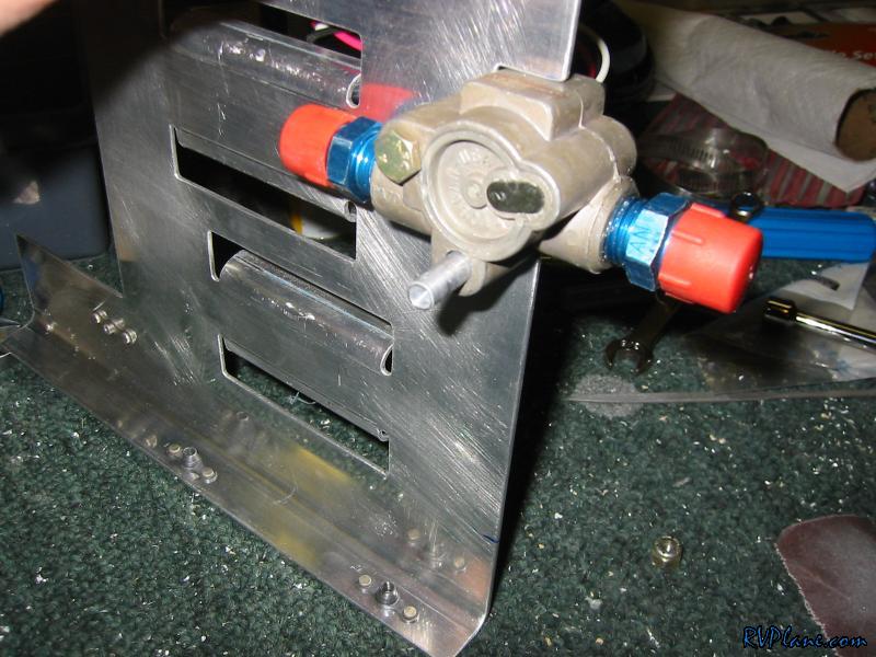 So I can't use bolts here because I don't have that much room between the bottom of the transducer and the floor. So I need to use a screw. To do so I needed to countersink the holes in the transducer slightly. I am sure this will void the warranty, but I don't care. Its a super clean install. 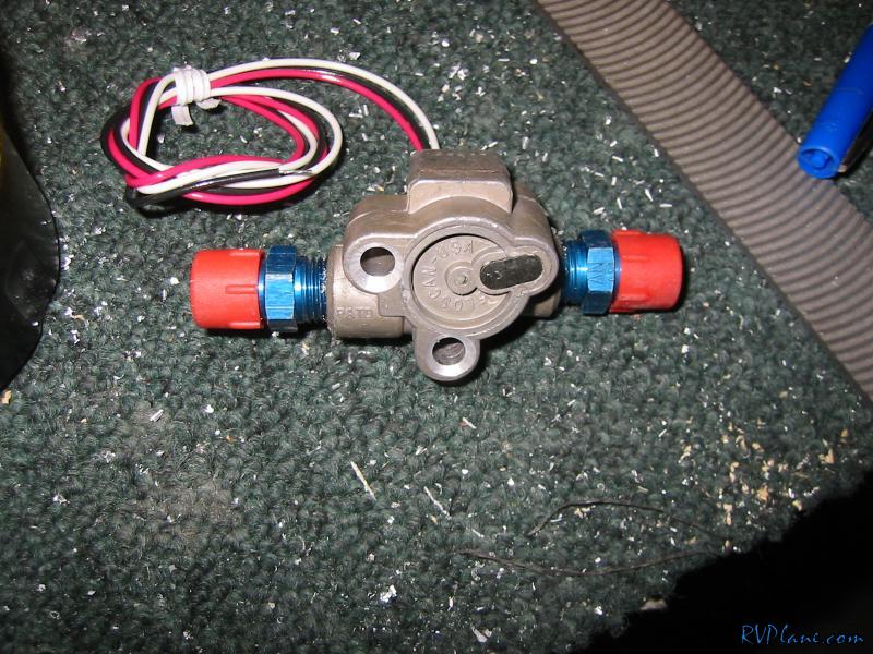 And the finished product. 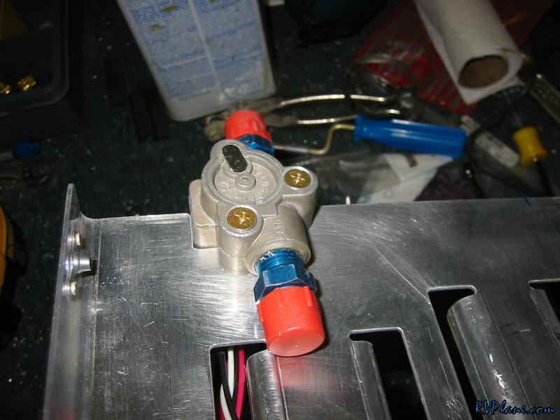 Looks and works great. 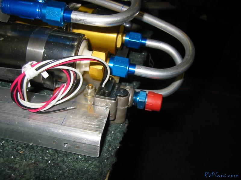 With the fuel flow transducer in place, I could run the fuel feed line from the manifold. 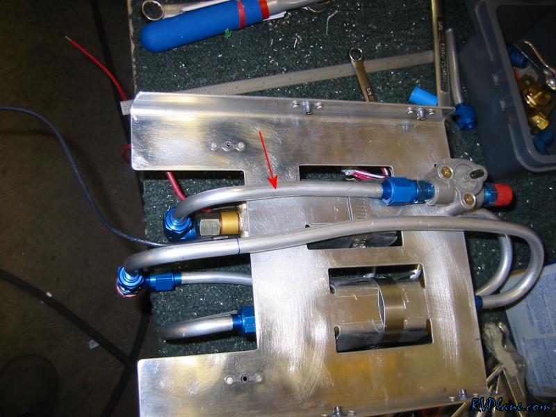 OK, the fitting to the right is the 90 degree elbow I forgot to take a pic of and talked about above. I don't know why I put an arrow to the tube on the left. Ignore that. 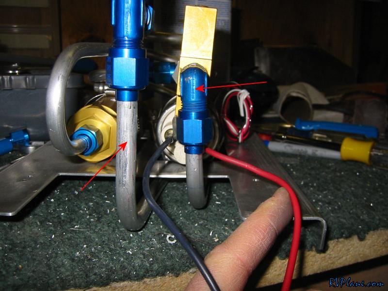 Finally was the line from the firewall to the fuel flow transducer. The tube ended up being a little on the long side, so that explains the funky route it has. 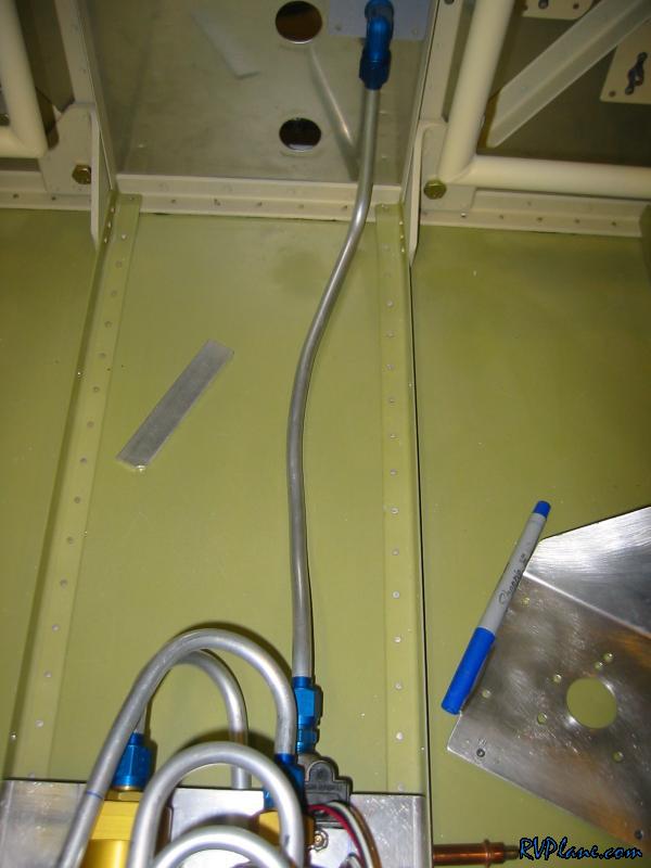 The only issue I have is a slight rubbing between the fuel line and the very front of the fuel pump cover. I will make a slight clearance hole to make sure this doesn't run through. So that's it for today. I got a lot more completed that I thought I could. Definitely a great day on the project. 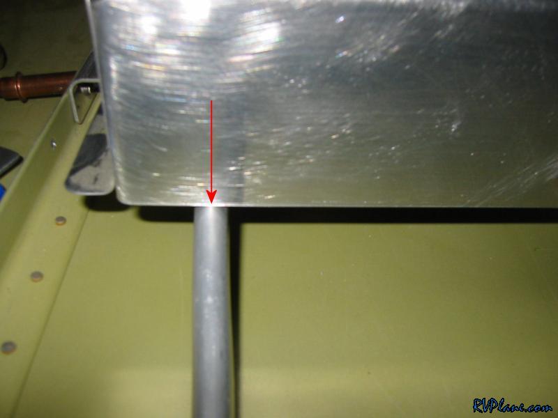
|
|||||
|
http://RVplane.com |
Last Modified: June 22, 2025 |