
|
 |
||||
On the aileron drawing, they talk about making a aileron stop that limits the upward travel of the aileron. It is basically some aluminum riveted to the inboard hinge bracket (wing side). This is supposed to hit the tubing that is on the bolt the short pushrod attaches to on the aileron. It's an OK idea, but I saw somewhere that someone had a better idea. That idea is to put a nylon spacer on that tubing, so the spacer rubs against the inboard bracket. So, on the way home from work I stopped by the local hardware store and picked up a 1/2" OD spacer. I forget what the ID was, but it was less than 5/16". I drilled out the inside to 5/16" so it would fit over the spacer. Here is the spacer after being drilled out and shortened. 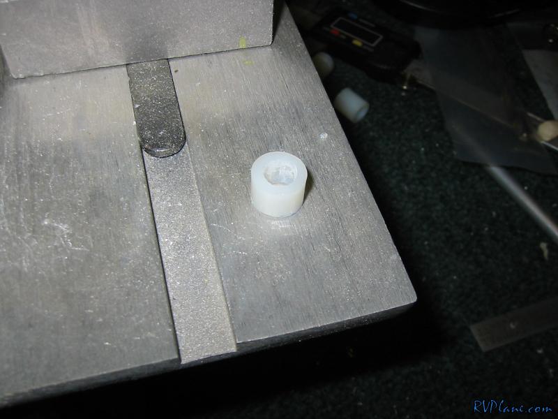 And here the aluminum spacer is inserted into the aluminum spacer. 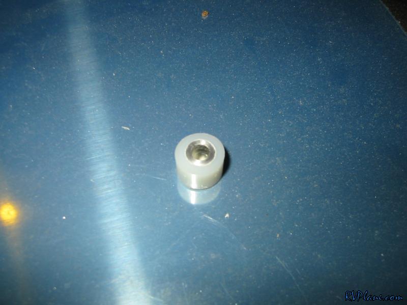 And installed. 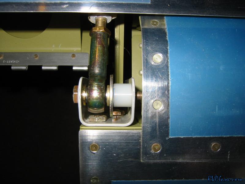 Unfortunately, it wasn't enough of a spacer. On the outboard bracket, a bolt was still rubbing on the bracket. I needed to go larger than 1/2". I taped some drill bits to the inboard bracket to simulate a larger spacer diameter. The aileron limits (up/down) were in the sweet spot when there was a #30 drill bit acting as a spacer. That means I needed a 3/4" diameter spacer. 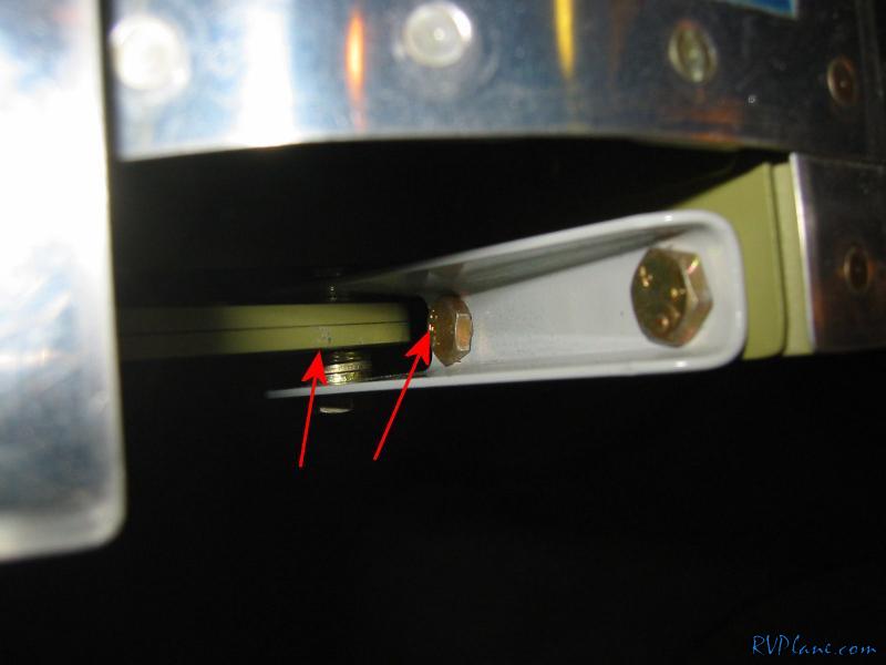 As luck would have it, I ran out to Home Depot, and in their aviation aisle there was a 3/4" OD 1/2" ID spacer! And this was in a drawer where they claimed the largest diameter was 1/2". Gotta love the disorganization of Home Depot. 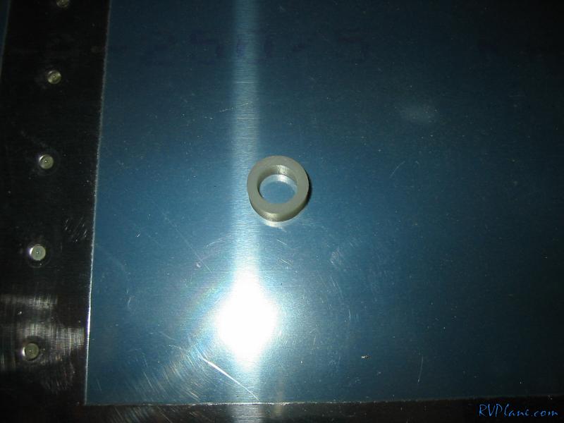 So, here is the end result - the aluminum spacer surrounded by two nylon spacers, giving a final outer diameter of 3/4" 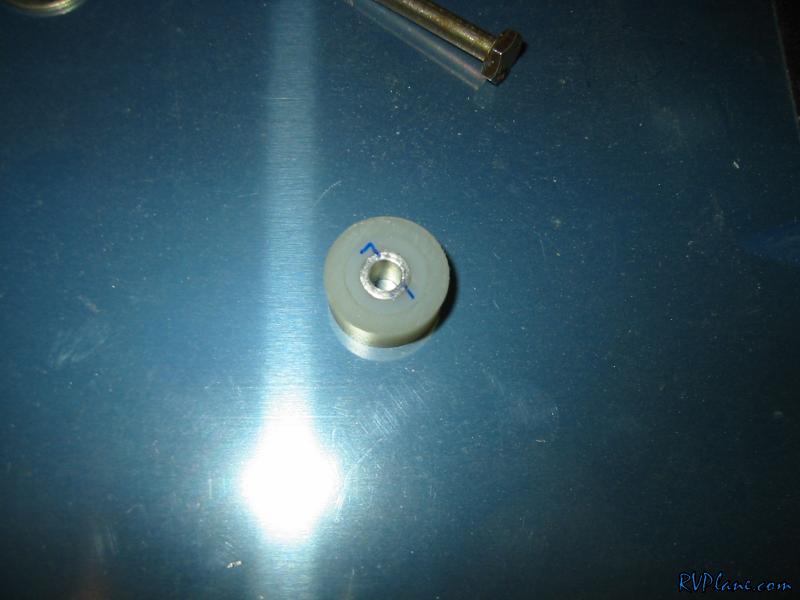 Using the digital level, I measured my up and down ranges of the ailerons - 29 degrees up and 16.8 degrees down. In chapter 15 (specifically page 15-2) Van's gives the maximum up/down travel of 32/17 and min up/down of 25/15. With those spacers, I ended up right towards the maximum....perfect! 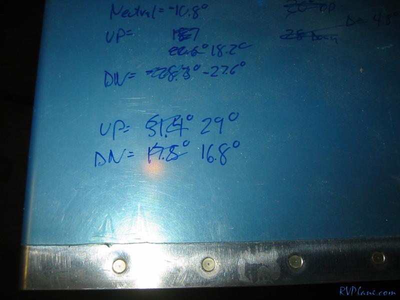 Next was onto the electric aileron trim. Although the manual trim is dirt simple and cheap, I didn't like the level positioned in the middle of the seats. I thought that room could be used for a fire extinguisher or something else. Plus its cool to have a china hat control on the grip to control both trim servos with the touch of your thumb. Anyways, I needed to put some holes and notches in the UHMW block. 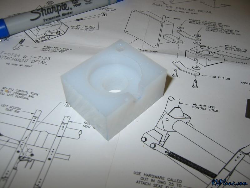 And also bevel an edge. 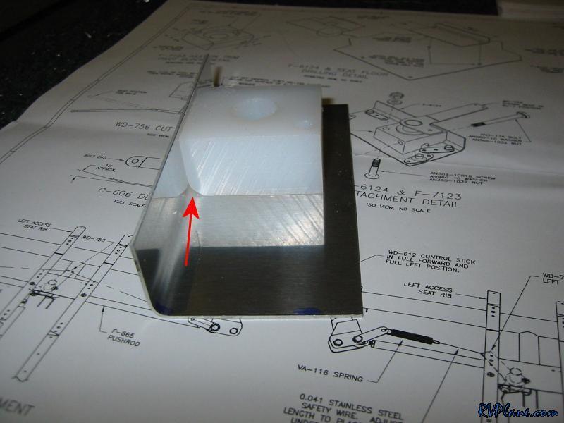 I shortened the bracket and backdrilled it using the right seat pan as a guide. 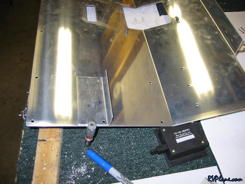 I then needed to remove two of the nutplates on the center two seat ribs. I think this is the first time I have drilled out rivets this year...wait, nevermind that, drilled out 4 perfectly good rivets. 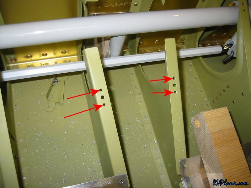 Next I marked where a new hole needs to go, 1 1/32" aft of the original #19 holes. I put a pilot #40 hole in there. 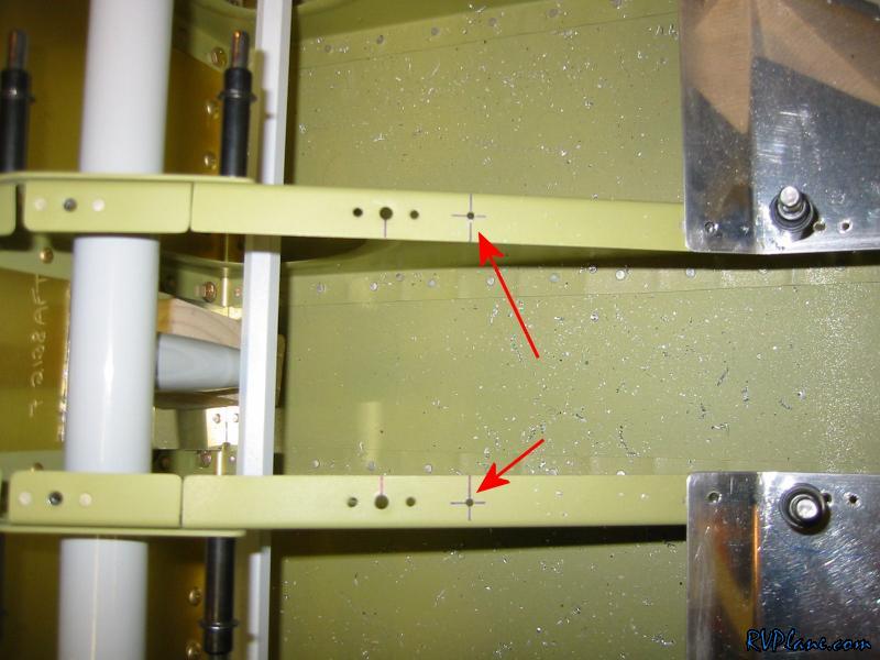 I clecoed on the bracket and enlarged the #40 holes to #19's for #8 screws. These holes actually get dimpled since the holes aren't duplicated in the seat ribs. This isn't so bad working on the install with the wings on. The wings give you a decent kneeling position to work here. That's enough fun for the night. 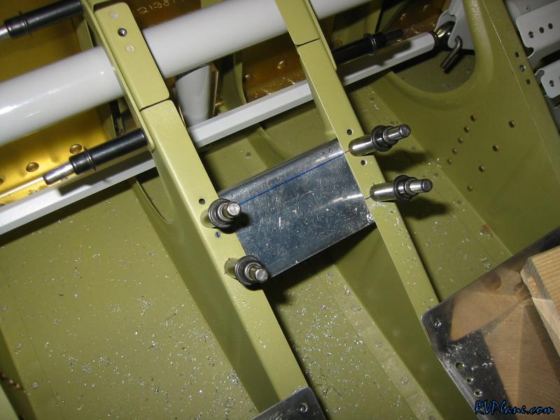
|
|||||
|
http://RVplane.com |
Last Modified: January 31, 2026 |